This article covers the steps to setup or troubleshoot an ethernet connection between a device with the Simcenter Anovis software and the Signal Recording Device (SRD) hardware.
The article is written from the vantage point that a component of an existing Simcenter Anovis system is being replaced. For example, a new computer, software re-installed, or replacing the SRD recording hardware.
Article Contents:
1. Overview
2. Ethernet setup
3. Configuring a new PC to match the SRD
4. Configuring a new SRD to match the PC
5. Configuring Anovis Signal Processing to match SRD
1. Overview
A typical Simcenter Anovis system has three locations where an IP (Internet Protocol) address is set for ethernet communiction between the PC with Anovis software and the SRD hardware:
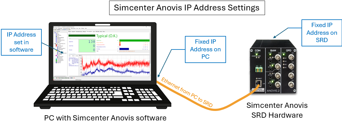
An IP address is a consists of four numbers (example: 192.168.192.20) that are used to identify members of a network. Some key information about IP addresses and Simcenter Anovis:
- Two IP addresses are used for the ethernet communication: one for the SRD, and one for the PC ethernet adaptor. These IP address must be different, but begin with the same three numbers (example: 192.168.192.X where X is unique number for the individual devices).
- Both addresses must be on the same subnet (example: 255.255.255.0) to communicate with each other.
- The IP address information in the Simcenter Anovis software must match the IP addresses set on the ethernet adaptor and the SRD hardware.
- A desired IP address for each should have been chosen and configured during the initial setup of the Anovis software. The default IP address of a Simcenter Anovis SRD is 192.168.192.20. This address might have been changed for a given installation.
In the event that the SRD or the PC that runs Simcenter Anovis are replaced, it is necessary to check that the IP configuration of the new device matches the intended setup. If backups are kept on hand, it is recommended to configure them in advance to avoid setup downtime.
2. Ethernet setup
The connection requires an ethernet connection (a direct connection or a connection via ethernet network structure, like switches etc.) linking the PC and the COM module of the SRD. When both ends of the cable are plugged in and the SRD is on, a green light should be visible in the COM module’s ethernet port.
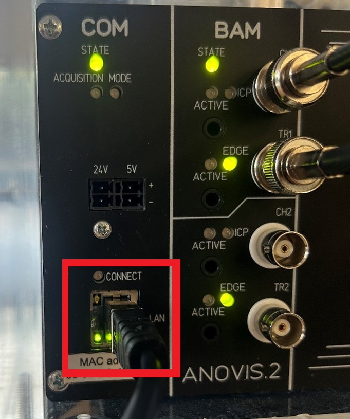
When the Simcenter Anovis software is running and a measurement setup is loaded, the light next to the word “CONNECT” should additionally turn on. If it does not, or if an error message is shown when attempting to use Simcenter Anovis. Use the following sections to adapt the configuration to the intended IP addresses as needed.
On a test bench, Simcenter Anovis is typically started by a command file, like EMOTStart.cmd. The command file also checks if the SRD is available at the defined address. If this is not the case, an error message occurs on startup:
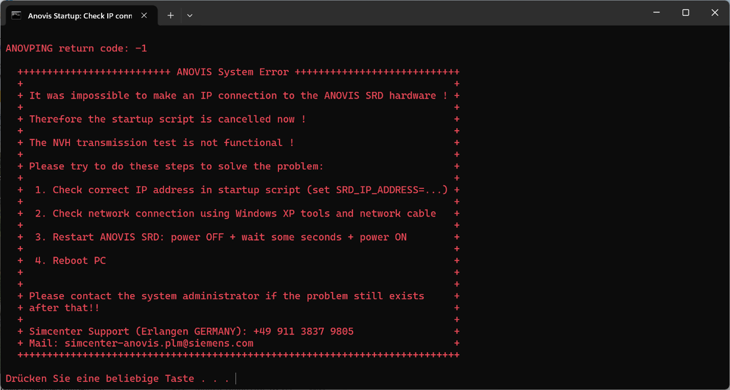
If the Ethernet IP address settings of a Simcenter Anovis system are not correct. the message "Impossible to make an IP connection to the ANOVIS SRD hardware" will appear.
Setting the IP addresses as shown below will avoid this message and allows Simcenter Anovis to start properly.
3. Configuring a new PC to match the SRD
If using an unconfigured computer, or if the SRD is known to already match its desired IP address, then the ethernet adapter on the PC will need to be configured to be on the same subnet as the SRD.
The first step is to determine the IP address of the SRD. If this information is not available from documentation of your custom Anovis setup, it can be viewed by connecting the SRD via an ethernet cable and running the “SRD Tool” application of the Simcenter Anovis software. This tool is located in the Start Menu folder that was chosen for Anovis during installation (ANOVIS.2 if the default folder was used). The program can also be found by searching for "SRD" in the Windows search.
When loaded, this tool will perform a UDP probe that will return the information of all SRD devices that are on and connected to the network the PC is on. If more than one unit is detected, the button “blink” can be used to identify the selected SRD. The lights on the COM board will blink for some seconds when the button is pressed.
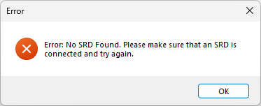
If the ethernet cable is not connected, or if the PC’s ethernet adapter is set to an identical IP address as the SRD, no connection will be established and a “No SRD Found” error message will appear. In this case, ensure that the ethernet cable is connected properly, and if so, adapt the PC’s ethernet adapter to a different value within the same subnet as shown below.
If an SRD is found, but in a condition that cannot currently be connected via TCP routing, then the following warning message will appear. This may occur if the PC and SRD are on a different subnet, if an active VPN software is rerouting the IP address, if an antivirus is blocking the SRDToolDialog, or there is an issue with the ethernet cable. However, even if this warning message appears, the tool will then proceed to show the configuration of the SRD(s) that were found, allowing the IP address to be read.
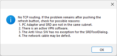
If the above warning appears, the tool will still proceed to show the configuration of the SRD(s) that were found, allowing the IP address to be read. If the configuration is shown without the error message, then the PC’s ethernet adapter IP address already matches the subnet of an SRD, though if multiple SRDs are on the network, it should still be checked that the subnet is the same as the desired SRD.
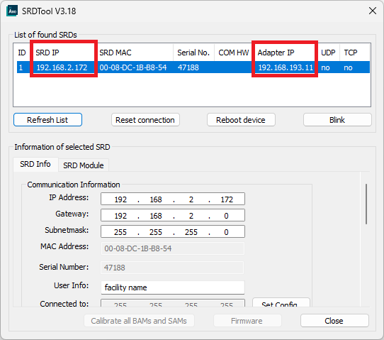
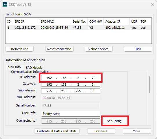
The SRD IP address and Adapter IP address columns should be compared to determine whether the two IP addresses are on the same subnet. In the above example, the first three numbers of the IP addresses are different, so the PC’s ethernet adapter would need to be edited to match the subnet of the SRD.
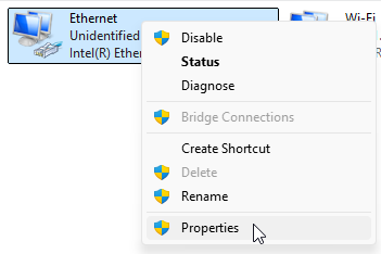
This can be accomplished by opening the Control Panel on Windows and navigating to the Network and Sharing Center, selecting the “Change adapter settings” option from the left-hand pane. Right click on the Ethernet option and select “Properties” from the context menu.
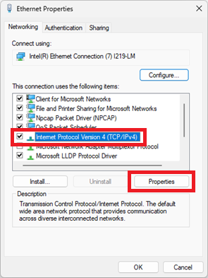
In the Properties dialog, ensure that the Internet Protocol Version 4 (TCP/IPv4) entry is checked. Select this line, then click the “Properties” button.
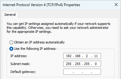
Select the “Use the following IP address” option, and enter the PC IP address that was chosen for your configuration. If this is not known, use an address and subnet mask such that the adapter is on the same subnet as, but not identical to, the IP address of your SRD.
To check the new configuration, run the SRD Tool a second time. The configuration information should show up without the TCP routing warning message.
4. Configuring a new SRD to match the PC
The SRD typically ships with a default IP address of 192.168.193.11. If a different IP address is to be used for your configuration, this can be changed by connecting the SRD via ethernet cable, running the SRD Tool as shown above, then selecting the line for the SRD, entering the desired IP address, and clicking on the “Set Config.” button.
If the SRD’s default IP address is on a different subnet than the PC adapter, you will need to temporarily change the PC adapter’s IP address to match the subnet of the SRD in order to set the configuration, then set it back once this has been completed. If this step is required, it is strongly recommended to write down the PC adapter’s ethernet address prior to making the change so that it can be changed back properly, and if possible, to do this from a Notebook or a computer other than the one for the test bench so that the test bench computer’s connectivity is not interrupted.
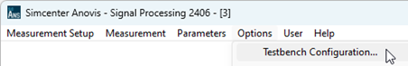
If the desired IP address for the SRD is not known but already configured, this can be viewed by running Anovis Signal Processing on the PC, opening its interface by clicking on the Anovis icon in the system tray. Select Options > Testbench Configuration… to open the Testbench Configuration window.
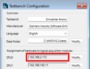
Then view the IP address for the corresponding SPU (Signal Processing Unit) index. Typically, this will be SPU0.
5. Configuring Anovis Signal Processing to match the SRD
In the event that both the PC and SRD have the desired IP addresses, but the address for the SRD is not set in the Anovis Signal Processing software (such as due to a reinstallation of the Anovis software), this can be configured by opening the Testbench Configuration window as shown above. Then, select the Modify… option for the corresponding SPU to open its dialog. If a measurement (*.ams) setup is currently open, you will need to close it prior to performing this step.
In the Testbench Configuration SPU dialog, click on the New… button, enter the desired IP address, and click Add. Then, highlight the new line and click Ok.
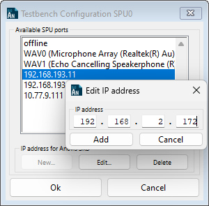
After making this change, be sure to click the Save button at the bottom of the Testbench Configuration window in order for the change to take effect.
Questions? Email peter.schaldenbrand@siemens.com (Americas) or olaf.strama@siemens.com (Europe and Asia).
Other Simcenter Anovis Resources:

